Stadium lighting control system: reference design for 220 floodlights
How to control 220 stadium floodlights across 4 locations
This reference design controls approximately 220 DMX512/RDM stadium floodlights across four corner pillars using one ArchiCORE Media central controller and four ArtGATE Rail network nodes connected by a fibre-optic ring, with 28 local DMX lines to the floodlight drivers.
A stadium lighting control system is not defined by the number of luminaires alone. Network topology, DMX line distribution, driver capabilities, control locations and redundancy requirements all influence the final architecture.
To show how these decisions connect, DITRA engineers developed a reference design based on real stadium tender requirements.
| Parameter | Value |
|---|---|
| Floodlights | ~220 white LED |
| Lighting locations | 4 corner pillars |
| Drivers per pillar | 50–55 DMX512/RDM |
| DMX universes | 1 per pillar, 4 total |
| DMX lines | 7 per pillar, 28 total |
| Drivers per line | ~8 |
| Central controller | ArchiCORE Media |
Stadium lighting control requirements: 220 floodlights, 4 pillars
The reference configuration includes approximately 220 white LED floodlights distributed across four pillars, with around 50–55 DMX512/RDM drivers at each location.
The outermost pillars are approximately 150 m apart.
Because the floodlights are white and only intensity is controlled, each driver uses one DMX channel.
The control system needs to support:
- 1–100% dimming;
- static and dynamic lighting scenes;
- schedules;
- central computer control;
- web access;
- communication between all four pillars;
- remote RDM access;
- integration with BMS and other systems;
- network redundancy where required.
The driver specification allows up to 32 drivers per physical DMX line.
Stadium lighting control architecture: ArchiCORE Media + ArtGATE Rail
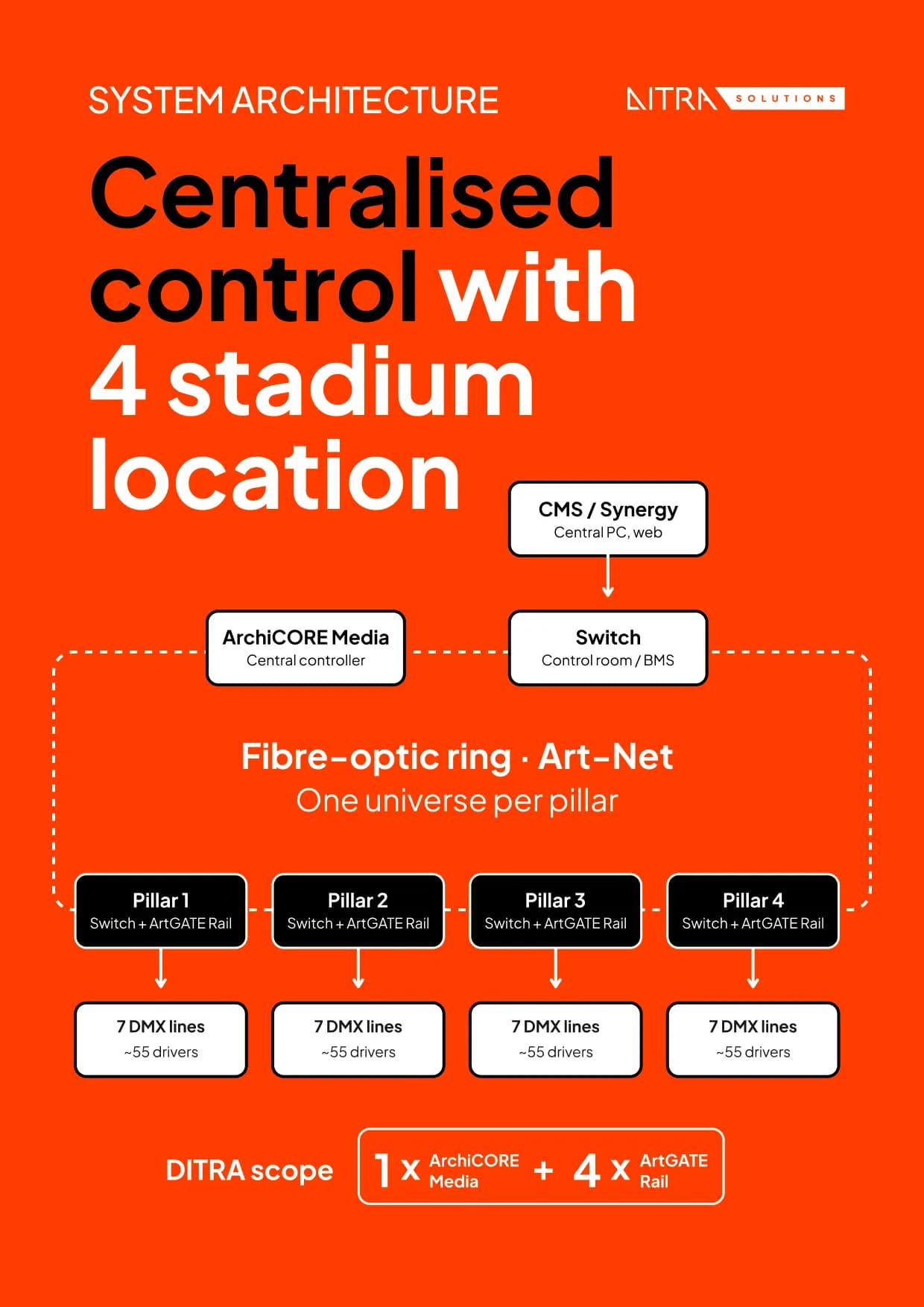
DITRA engineers structured the reference architecture around one central controller and four local network-to-DMX/RDM nodes.
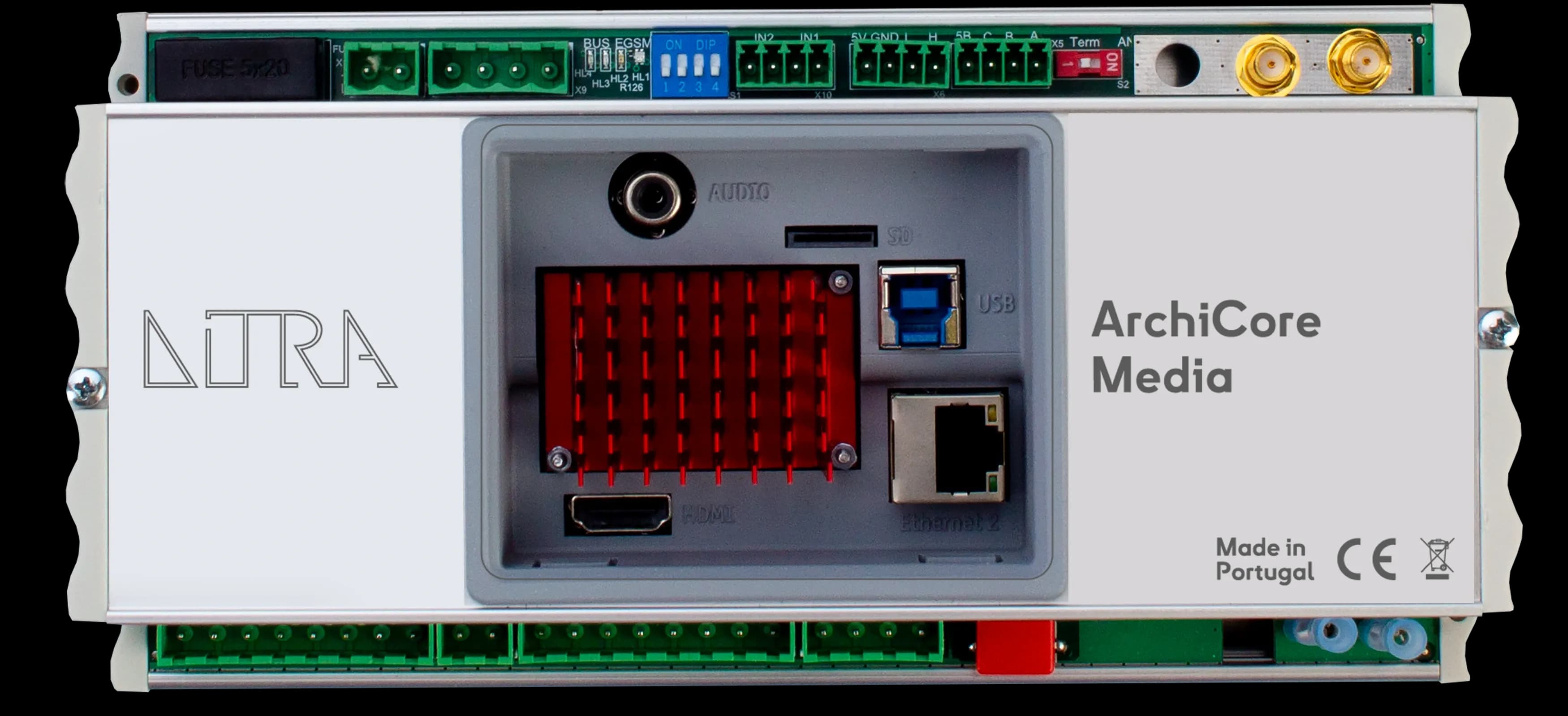
1 × ArchiCORE Media
ArchiCORE Media provides:
- central system control;
- scene management;
- schedules;
- integration with BMS and other systems;
- distribution of Art-Net data across the stadium network.
If astronomical control is required, it can be handled through the final controller and software configuration.
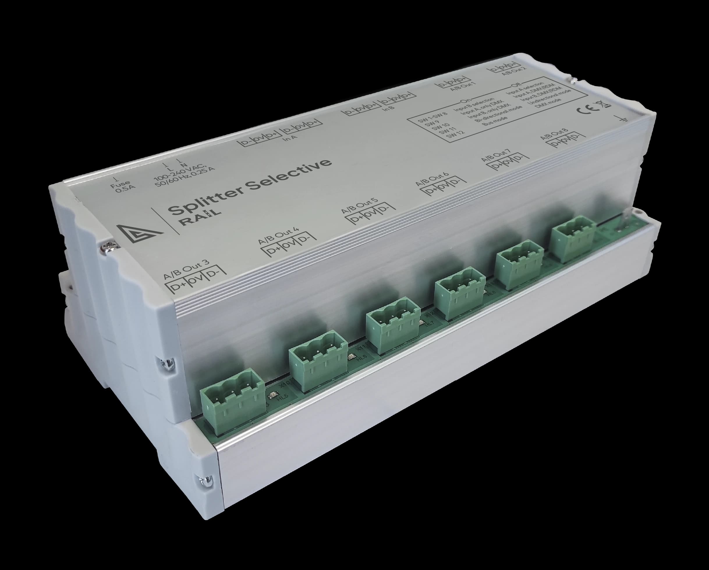
4 × ArtGATE Rail
One ArtGATE Rail is installed at each pillar.
Each unit receives Art-Net from the stadium network and provides local DMX/RDM outputs to the floodlight drivers.
28 physical DMX lines
Each pillar uses 7 physical DMX lines.
With approximately 50–55 drivers per pillar, this results in around 8 drivers per line.
Fibre-optic ring between stadium pillars
The four pillars are spread around the stadium, with about 150 m between the outermost ones, and all need to connect to one control room.
Ethernet over a fibre-optic ring provides a redundant communication path between the locations and carries network-based control and RDM access, while DMX remains local to each pillar.
For redundant ring operation, the network switches should support a fast-recovery protocol such as ERPS or MRP.
Lighting control software: LiteFORM, CMS, Synergy
LiteFORM
for creating static and dynamic lighting scenes.
CMS
for scene management, schedules and monitoring.
Synergy
for browser-based access and operation.
Why this stadium lighting control architecture works
How many DMX universes does each pillar need?
Each pillar needs only one DMX universe for this configuration. Approximately 55 white floodlights require approximately 55 DMX channels. One DMX universe contains 512 channels.
So: 55 channels used out of 512
Across four pillars: 4 pillars = 4 DMX universes
DMX universe capacity and physical DMX line distribution, however, solve different engineering problems.
Why 7 physical DMX lines per pillar?
Each pillar uses 7 DMX lines for fault isolation, not because additional channel capacity is required.
The minimum number of physical lines for 55 drivers, with a limit of 32 drivers per line, is two.
With only two lines, each line would carry approximately 28 drivers.
If one line failed, approximately half of the floodlights at that pillar would be affected.
With 7 lines: 55 ÷ 7 ≈ 8 drivers per line
A single line failure therefore affects approximately eight floodlights instead of around 28.
One DMX universe handles the data. The physical DMX lines determine the size of a possible line failure.
Remote RDM access to stadium floodlight drivers
RDM allows compatible floodlight drivers to be accessed through the stadium network for commissioning and maintenance.
From the central control environment, engineers can:
- discover a driver;
- identify the corresponding floodlight;
- assign its DMX address;
- configure supported parameters;
- replace a driver by finding the new device by UID and assigning the previous address.
This reduces the need for local intervention at every pillar during commissioning and maintenance.
What happens if part of a stadium lighting control system fails?
Fibre ring interruption
With ERPS, MRP or another suitable fast-recovery protocol, traffic is rerouted through the alternative path of the fibre ring.
One DMX line failure
Only the drivers connected to that physical segment are affected.
In this reference architecture, that is approximately eight floodlights.
Central controller failure
Controller redundancy can be added if the project requires continued central operation after a controller failure.
Loss of communication to one pillar
The required local behaviour must be defined during detailed design and verified against the confirmed fallback capabilities of the selected ArtGATE Rail configuration and floodlight drivers.